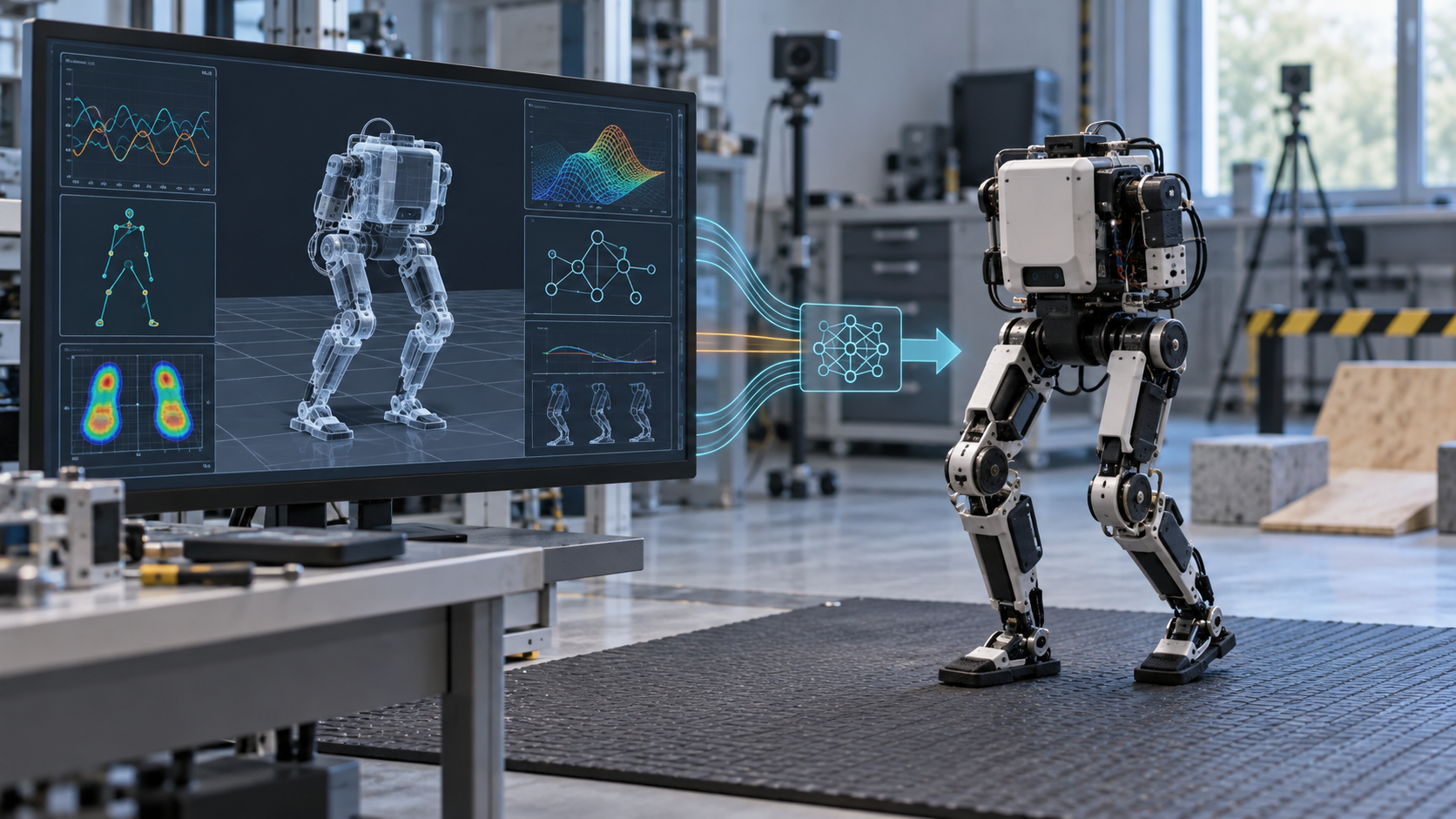
Sim-to-real for a small biped robot is the process of building and training a controller in simulation, then transferring it to physical hardware without assuming the two systems behave identically. A reliable workflow starts with a measured robot model, a defined observation-and-action contract, realistic actuator and timing behavior, and staged hardware tests. The exported policy file is only one output; you also need the calibration, runtime configuration, safety limits, and evidence that simulation and hardware respond similarly.
If you are still mapping the hardware stack, start with our guide to what makes a small biped robot work. This article focuses on the control workflow after a robot can be assembled, powered, sensed, and commanded safely.
Key facts
- Sim-to-real is a systems problem, not a model-export step. Geometry, mass, actuator response, sensors, timing, contacts, software preprocessing, and safety limits all affect transfer.
- Start by matching the robot you actually built. A visually accurate simulation can still be dynamically wrong.
- System identification and domain randomization solve different problems: identification improves the nominal model; randomization trains robustness around uncertain parameters.
- Keep the observation order, units, normalization, action order, control frequency, and clipping behavior identical between training and deployment.
- Validate in stages: offline replay, simulator parity, single-joint or supported tests, restrained whole-body tests, then low-energy free motion.
- A policy that walks one robot is not automatically compatible with another robot that uses the same simulator or model format.
- MechaSeed has not independently reproduced the workflow below on its own prototype. The steps combine established robotics practice with published project documentation.
What goes into a sim-to-real workflow?
The useful input is not simply a CAD model. It is a versioned description of the physical system and the controller contract.
For the robot, record link geometry, joint axes, limits, masses, centers of mass, inertia, collision shapes, foot geometry, actuator type, transmission assumptions, and the location and orientation of every sensor. For the runtime, record the control rate, sensor rate, command latency, observation vector, normalization constants, action representation, action scale, clipping limits, and fallback behavior.
The expected output is a deployable controller package. That usually includes the trained policy, preprocessing and postprocessing code, robot configuration, joint offsets, model version, test logs, and a checklist for safe startup. ONNX can be one policy format, but the format does not make the policy portable by itself.
A practical sim-to-real workflow
1. Freeze the hardware and control contract
Choose one robot revision before training. Assign stable names and indices to every joint, then document positive rotation direction, zero position, safe range, and the command type expected by each actuator. Confirm the coordinate frames for the torso, IMU, feet, and world.
Define the controller contract just as precisely. List every observation in order, with its unit and reference frame. List every action in order and state whether it represents a target position, position offset, velocity, torque, or another command. Fix the policy and actuator update rates and decide how delayed, missing, or out-of-range data will be handled.
This prevents a common failure: the neural network runs successfully, but the runtime feeds it different values than the training environment did.
2. Build the dynamics model, not just the visual model
URDF and MJCF can both describe articulated robots, while MuJoCo uses MJCF as its native model format and can also load URDF. The MuJoCo modeling guide explains the kinematic tree and model elements behind that representation.
Check these elements before tuning rewards:
- measured or carefully estimated link mass and center of mass;
- inertia that reflects the printed part, electronics, fasteners, wiring, and battery placement;
- correct joint axes, limits, and neutral pose;
- simple, stable collision geometry around the feet and limbs;
- ground and foot friction that produce plausible slip;
- actuator force or torque limits that the real hardware can sustain;
- a simulation timestep and controller rate that remain stable together.
A beautiful mesh cannot compensate for incorrect mass or joint direction. Use visual meshes for appearance and separate simplified collision geometry when practical.
3. Identify actuators and timing
Small bipeds are especially sensitive to actuator mismatch. Low-cost bus servos can include backlash, deadband, internal control loops, speed limits, voltage-dependent response, thermal limits, and communication delay. A simple ideal position actuator often reacts faster and more consistently than the real mechanism.
Collect controlled hardware measurements before whole-body walking tests. Command small, safe trajectories while logging the requested position, measured position, velocity if available, current or load proxy if available, supply voltage, and timestamps. Repeat at more than one speed and direction so that friction and delay are visible.
Use those measurements to estimate the nominal actuator behavior and end-to-end latency. The influential 2018 sim-to-real locomotion study combined system identification, an actuator model, latency simulation, perturbations, and environment randomization. That result was demonstrated on a quadruped, but the engineering lesson also applies to small bipeds: policy robustness cannot rescue a simulator that ignores the dominant hardware behavior.
4. Calibrate sensors and capture a real baseline
Verify the IMU orientation while the robot is motionless and while it is rotated around each axis. Confirm joint offsets in a repeatable reference pose. Test foot-contact sensors individually. Log standing data long enough to see sensor bias, noise, packet timing, and drift.
Save a short real-hardware dataset before training. It gives you something concrete to replay through the observation pipeline and compare with simulation. Without this baseline, a transfer failure can be mistaken for a learning problem when the actual cause is an axis swap, unit conversion, stale packet, or incorrect offset.
5. Train for the task and for measured uncertainty
Start with a task the physical robot can survive failing. Standing, posture recovery within a narrow range, or slow stepping is easier to diagnose than aggressive walking.
Build rewards around the behavior you need: command tracking, upright orientation, controlled foot contact, smooth actions, joint-limit avoidance, and reasonable energy use. Inspect the learned behavior instead of trusting one reward total. A policy can exploit a simulator in ways that produce a high score but impossible hardware motion.
Then randomize the parameters that are uncertain in reality. Useful candidates include mass, center of mass, friction, motor strength, damping, control latency, sensor noise, observation delay, terrain height, and initial pose. Use ranges informed by measurements or credible tolerances. Randomization that is too narrow produces a brittle policy; randomization that is unrealistically broad can make learning unnecessarily difficult or hide a bad nominal model.
6. Prove runtime parity before powering the robot
Export the trained controller and run it outside the training process against recorded observations. Compare its outputs with the original training implementation. If ONNX is used, follow the ONNX Runtime workflow to load and run the exported model, then validate accuracy and performance on the target runtime.
Check more than whether the file loads:
- tensor names, shapes, data types, and batch dimensions;
- observation order, units, and normalization;
- recurrent state initialization, if the policy has memory;
- action scale, clipping, filtering, and joint mapping;
- inference time and control-loop jitter on the onboard computer;
- behavior when a sensor value is missing, late, NaN, or outside the training range.
Run the same recorded observation sequence through both implementations and set a numerical tolerance for output differences. This separates model-export errors from physics-transfer errors.
7. Deploy in controlled stages
Do not make first contact with reality during an unrestricted walking test. Use a progression that limits stored energy and fall distance:
- Confirm the emergency stop, current or temperature limits, and a known safe pose.
- Test joint direction and range with the robot unpowered where possible, then at low command amplitude.
- Test one joint or one leg while the robot is securely supported.
- Run the complete observation pipeline without sending actions and inspect the logs.
- Run the policy with reduced action scale while the robot is restrained above a clear surface.
- Test standing and small disturbances before commanded walking.
- Move to low-speed free motion on a flat, high-friction test area with a spotter or tether appropriate to the robot.
Record commands, observations, inferred actions, measured motion, battery voltage, faults, and timestamps from the first run. Video is helpful, but synchronized logs are what let you compare the same event with simulation.
How to diagnose a transfer failure
Change one category at a time. Retraining immediately can bury a configuration defect inside a new policy.
The robot moves violently at startup
First check joint order, sign, offsets, units, action scale, neutral pose, and observation normalization. A structural mismatch is more likely than insufficient training when the failure is immediate and repeatable.
The robot is stable in simulation but oscillates on hardware
Inspect actuator gain, delay, action filtering, control-loop timing, backlash, and battery voltage. The simulated actuator may be too responsive or the real loop may have more latency and jitter.
The feet slip or the robot falls at contact
Inspect foot collision geometry, friction, contact timing, center of mass, IMU frame, and floor material. Do not tune one friction value to match every surface; document the tested surface and train for a justified range.
The first steps work and performance then degrades
Check thermal behavior, voltage sag, communication errors, accumulating state-estimation drift, and recurrent-state handling. A short simulation episode may not expose effects that build over time.
Open Duck Mini v2 as a public example
Open Duck Mini v2 exposes much of this chain in public. Its sim-to-real notes describe an MJCF model with mass and inertia, actuator identification, MuJoCo parameters such as damping and force range, reward design, noise, and randomization. The maintainers explicitly label those notes “not finalized yet” and warn that inexpensive servomotors are difficult to model.
The project’s runtime documentation covers IMU checks, motor checks, joint offsets, and an ONNX walking-policy command. Its separate pre-policy checklist checks joint positions and offsets, IMU orientation, and foot switches, while also retaining a TODO for greater automation. Treat these resources as a project-specific example, not a universal or complete safety standard.
If you are evaluating that build route, read our MicroDuck vs Open Duck Mini v2 comparison and Open Duck Mini v2 cost guide. MechaSeed has not independently tested the published policies or reproduced their transfer results.
Where MechaSeed’s Agent Core concept fits
MechaSeed is exploring an Agent Core concept intended to reduce repeated integration work around actuators, sensing, compute, control, configuration, and reference calibration for a body the builder is legally allowed to print. A profile-matched core could make the hardware and runtime contract easier to reproduce, but it would not eliminate robot-specific modeling, validation, or safety work.
This remains Stage 1 demand validation. No Body Profile, actuator model, SDK, controller compatibility, performance, price, or delivery plan has been validated. If inconsistent hardware integration is the part of sim-to-real you most want to avoid, review the Agent Core concept and join the research waitlist. The waitlist is not an order or pre-order.
Frequently asked questions
Does sim-to-real require reinforcement learning?
No. The same gap appears with model-based control, trajectory optimization, imitation learning, and hand-designed controllers. Reinforcement learning makes the issue visible because it can exploit subtle simulator behavior, but accurate models, timing, calibration, and staged validation matter for any controller.
Is an ONNX file enough to run a policy on a real robot?
No. ONNX packages the model graph and parameters. You still need identical inputs, preprocessing, recurrent state handling, action mapping, timing, hardware configuration, and safety limits.
Can a policy for one small biped run on another?
Assume it cannot until compatibility is demonstrated. Similar height or joint count does not guarantee matching geometry, joint order, actuator response, sensors, observation space, action space, control rate, or normalization.
Should I improve model accuracy or add more domain randomization?
Fix known structural errors first, identify the dominant dynamics, then randomize the remaining uncertainty. Randomization is not a substitute for a wrong joint axis, incorrect action scale, or missing latency.
How do I know a policy is ready for unrestricted testing?
There is no single score. Require documented simulator tests, runtime-parity checks, safe response to invalid inputs, supported-hardware tests, restrained whole-body tests, repeatable standing behavior, and a reviewed stop procedure. Expand the test envelope gradually and keep the conditions and logs for every step.
Last fact-check: September 20, 2026. This is an educational workflow, not a certification or project-specific safety procedure. The cover is an AI-generated engineering visualization of a generic robot and does not depict MechaSeed hardware or a completed MechaSeed test.